Select your location
-
-
Australia Bangladesh Brunei Cambodia China Fiji, Tonga French Polynesia Hong Kong, China India Indonesia (Bahasa) Indonesia (English) Japan Kazakhstan Korea, South Laos Malaysia Maldives Mongolia Mongolia (English) Myanmar (English) New Caledonia New Zealand Papua New Guinea Philippines Singapore Sri Lanka Taiwan, China Thailand (English) Thailand (Thai) Uzbekistan Uzbekistan (English) Vietnam Vietnam (Vietnamese)
-
Albania Austria Belarus Belarus (English) Belgium Belgium (Dutch) Bosnia-Herzegovina Bulgaria Croatia Cyprus Czech Republic Denmark Estonia Finland France Georgia Georgia (English) Germany Greece Hungary Ireland Italy Kosovo Latvia Lithuania Malta Moldavia Montenegro Netherlands North Macedonia Norway Poland Portugal Romania Russia Serbia Slovakia Slovenia Spain Sweden Switzerland (French) Switzerland (German) Turkey Ukraine (Ukrainian) United Kingdom
-
-
Algeria Azerbaijan (Azerbaijani) Azerbaijan (English) Bahrain (English) Benin Botswana Burkina Faso Cameroon Central African Republic Chad Comoros Congo Dem. Rep. Congo (Zaire) Egypt and North East Africa (Arabic) Egypt and North East Africa (English) Equatorial Guinea Francophone Africa Gabon Gambia Ghana Guinea Iraq Israel Ivory Coast Jordan Kenya Kuwait Lebanon Liberia Libya Madagascar Malawi Mali Mauritania Mauritius Mayotte Morocco Mozambique Namibia Niger Nigeria Oman Pakistan Qatar Reunion Saudi Arabia (Arabic) Saudi Arabia (English) Senegal Seychelles Sierra Leone South Africa Swaziland Tanzania Togo Tunisia Uganda United Arab Emirates Yemen Zambia Zimbabwe
-
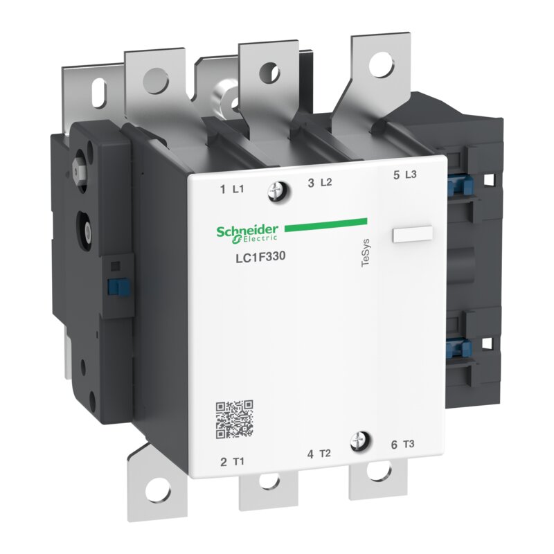
Leistungsschütz LC1F 3p, 160 kW, 330 A, 400 V AC3
LC1F330
Eingestellt am: 05. April 2023

EAN Code: 3389110230895
Hauptdokumente
| Download | |
|
|
Download |
|
|
Download |
|
|
Download |
|
|
Download |
|
|
Download |
|
|
Download |
|
|
Download |
|
|
Download |
|
|
Download |
|
|
Download |
|
|
Download |
Dieses Produkt ist kompatibel mit
Zusatzausrüstungen: Kompatible Produkte
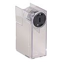
 Zusatzausrüstungen (1)
Spezifikationen
| Hauptmerkmale | |
|---|---|
| Baureihe | TeSys |
| Produktname | TeSys F |
| Produkt- oder Komponententyp | Schütz |
| Kurzbezeichnung des Geräts | LC1F |
| Anwendung des Schützes | Motorsteuerung Ohmsche Last |
| Nutzungskategorie | AC-4 AC-3 AC-1 |
| Beschreibung der Pole | 3P |
| Strommast Kontaktzusammensetzung | 3 S |
| [Ue] Bemessungs-Betriebsspannung | <= 1.000 V AC 50/60 Hz <= 460 V DC |
| [Ie] Bemessungs-Betriebsstrom | 400 A (bei <40 °C) bei <= 440 V AC AC-1 330 A (bei <55 °C) bei <= 440 V AC AC-3 |
| Motorleistung (kW) | 160 kW bei 1.000 V AC 50/60 Hz (AC-3) 160 kW bei 380 - 400 V AC 50/60 Hz (AC-3) 180 kW bei 415 V AC 50/60 Hz (AC-3) 200 kW bei 440 V AC 50/60 Hz (AC-3) 200 kW bei 500 V AC 50/60 Hz (AC-3) 100 kW bei 220 - 240 V AC 50/60 Hz (AC-3) 220 kW bei 660 - 690 V AC 50/60 Hz (AC-3) 59 kW bei 400 V AC 50/60 Hz (AC-4) |
Zusatzmerkmale |
| Steuerkreisspannung | 24...1000 V AC 40 - 400 Hz with LX1/LX9 coil 24...460 V DC with LX4 coil 100 - 250 V AC 50/60 Hz with LXE coil 100...380 V DC with LXE coil |
| [Uimp] Bemessungs-Stoßspannungsfestigkeit | 8 kV |
| Überspannungskategorie | III |
| [Ith] Konventioneller thermischer Strom in freier Luft | 400 A (bei 40 °C) |
| [Irms] Bemessungseinschaltvermögen | 3300 A AC entspricht IEC 60947-4-1 |
| Nenn-Unterbrechungskapazität | 2640 A entspricht IEC 60947-4-1 |
| [Icw] Bemessungs-Kurzzeitstromfestigkeit | 2650 A 40 °C - 10 s 1800 A 40 °C - 30 s 1300 A 40 °C - 1 min 900 A 40 °C - 3 min 750 A 40 °C - 10 min |
| Zugehörige Absicherung | 400 A aM bei <= 440 V 500 A gG bei <= 440 V |
| Durchschnittliche Impedanz | 0,28 MOhm - Ith 400 A 50 Hz |
| [Ui] Bemessungs-Isolationsspannung | 1000 V entspricht IEC 60947-4-1 1500 V entspricht VDE 0110 Gruppe C |
| Verlustleistung pro Pol | 44 W AC-1 31 W AC-3 |
| Steuerkreisspannungsgrenzen | Betrieb: 0,85 - 1,1 Uc AC 40 - 400 Hz with LX1/LX9 coil Abfallspannung: 0,35 - 0,55 Uc AC 40 - 400 Hz with LX1/LX9 coil Betrieb: 0,85 - 1,1 Uc DC with LX4 coil Abfallspannung: 0,15 - 0,2 Uc DC with LX4 coil Betrieb: 85...275 V AC 50/60 Hz with LXE coil Abfallspannung: 0...60 V AC 50/60 Hz with LXE coil Betrieb: 85...418 V DC with LXE coil Abfallspannung: 0...45 V DC with LXE coil |
| Wärmeabgabe | 8 W 2,2…5,5 W |
| Betriebszeit | 40 - 65 ms Schließung für with LX1/LX9 coil 100 - 170 ms Öffnung für with LX1/LX9 coil 40 - 50 ms Schließung für with LX4 coil 40 - 65 ms Öffnung für with LX4 coil 40 - 80 ms Schließung für with LXE coil 6...54 ms Öffnung für with LXE coil |
| Montagehalterung | Platte |
| Normen | IEC 60947-4-1 JIS C8201-4-1 EN 60947-1 IEC 60947-1 EN 60947-4-1 |
| Produktzertifizierungen | ABS CSA UL RMRoS DNV CB BV LROS (Lloyds register of shipping) RINA UKCA |
| Anschlüsse - Klemmen | Stromkreis: Ringkabelschuhklemmen 1 Kabel(n) 240 mm² Stromkreis: Schiene 2 Kabel(n) - Schienenquerschnitt: 30 x 5 mm Steuerkreis: Schraubklemmen 1 Kabel(n) 1…4 mm²flexibel ohne Kabelende Steuerkreis: Schraubklemmen 2 Kabel(n) 1…4 mm²flexibel mit Kabelende Steuerkreis: Schraubklemmen 1 Kabel(n) 1…4 mm²flexibel mit Kabelende Steuerkreis: Schraubklemmen 2 Kabel(n) 1…2,5 mm²starr ohne Kabelende Steuerkreis: Schraubklemmen 1 Kabel(n) 1…4 mm² Steuerkreis: Schraubklemmen 2 Kabel(n) 1…4 mm² Steuerkreis: Schraubklemmen 1,0 Kabel(n) 0,2…2,5 mm²flexibel ohne Kabelende Steuerkreis: Schraubklemmen 1,0 Kabel(n) 0,25…2,5 mm²flexibel mit Kabelende Steuerkreis: Schraubklemmen 1,0 Kabel(n) 0,2…2,5 mm²starr ohne Kabelende |
| Anzugsdrehmoment | Stromkreis: 35 Nm Steuerkreis: 1,2 Nm Steuerkreis: 0,6 Nm |
| Mechanische Lebensdauer | 10 Mcycles |
| Anzugsleistung in VA | 600…700 VA, 40 - 400 Hz cos phi 0,9 (at 20 °C)with LX1/LX9 coil 655…803 VA (at 20 °C)with LX4 coil 300…350 VA, 50/60 Hz cos phi 0,5 (at 20 °C)with LXE coil 300…310 VA (at 20 °C)with LXE coil |
| Halteleistungsaufnahme in VA | 8…10 VA, 40 - 400 Hz cos phi 0,9 (at 20 °C)with LX1/LX9 coil 3,68…4,53 VA (at 20 °C)with LX4 coil 4,5…7,0 VA, 50/60 Hz cos phi 0,5 (at 20 °C)with LXE coil 2,5…4,0 VA (at 20 °C)with LXE coil |
| Max. Betriebsrate | 2400 cyc/h 55 °C |
| Kompatibilitätscode | LC1F | Montage |
| Schutzart (IP) | IP20 Vorderseite mit Schutzabdeckungen entspricht IEC 60529 IP20 Vorderseite mit Schutzabdeckungen entspricht VDE 0106 |
| Beschichtung | TH |
| Umgebungstemperatur bei Betrieb | -5…55 °C |
| Umgebungstemperatur bei Lagerung | -60…80 °C |
| Geräte-Umgebungstemperatur | -40…70 °C |
| Aufstellungshöhe | 3.000 m ohne Leistungsreduzierung |
| Mechanische Robustheit | Schwingungen Schütz geöffnet: 2 Gn, 5 - 300 Hz Schwingungen Schütz geschlossen: 5 Gn, 5 - 300 Hz Schocks Schütz geöffnet: 6 Gn für 1/2-Sinuswelle (11 ms) Schocks Schütz geschlossen: 15 Gn für 1/2-Sinuswelle (11 ms) |
| Höhe | 206 mm |
| Breite | 213 mm |
| Tiefe | 219 mm |
| Produktgewicht | 9,5 kg | Verpackungseinheiten |
| VPE 1 Art | PCE |
| Anzahl der Geräte pro Packung | 1 |
| VPE 1 Höhe | 25,000 cm |
| VPE 1 Breite | 25,000 cm |
| VPE 1 Länge | 35,000 cm |
| Verpackungsgewicht (Lbs) | 8,420 kg |
| VPE 2 Art | P06 |
| VPE 2 Menge | 10 |
| VPE 2 Höhe | 75,000 cm |
| VPE 2 Breite | 60,000 cm |
| VPE 2 Länge | 80,000 cm |
| VPE 2 Gewicht | 93,720 kg | Vertragliche Gewährleistung |
| Garantie (in Monaten) | 18 |
Nachhaltigkeit
Nachhaltigkeit
|
Quecksilberfrei
|
Ja |
| Verpackung ohne Kunststoff | Nein |
| Verpackung mit Recycling-Karton | Ja |
| Rücknahme | Nein |
| CO2-Bilanz (kg CO2 eq.) | 2461 |
| Total lifecycle Carbon footprint | 2 461 kg CO2 eq. |
| Carbon footprint of the manufacturing phase [A1 to A3] | 52.30365849 |
| CO₂-Fußabdruck der Herstellungsphase [A1 bis A3] | 52 kg CO2 eq. |
| Carbon footprint of the distribution phase [A4] | 2.853739668 |
| CO₂-Fußabdruck der Distributionsphase [A4] | 3 kg CO2 eq. |
| Carbon footprint of the installation phase [A5] | 0.022932335 |
| CO₂-Fußabdruck der Installationsphase [A5] | 0 kg CO2 eq. |
| Carbon footprint of the use phase [B2, B3, B4, B6] | 2389.675884 |
| CO₂-Fußabdruck der Nutzungsphase [B2, B3, B4, B6] | 2 390 kg CO2 eq. |
| Sustainable packaging | Nein |
| Carbon footprint of the end-of-life phase [C1 to C4] | 16.45078379 |
| CO₂-Fußabdruck der End-of-Life-Phase [C1 bis C4] | 16 kg CO2 eq. |
| WEEE-Kennzeichnung | Das Produkt muss entsprechend bestimmter Hinweise auf Märkten der Europäischen Union entsorgt werden und darf nicht in Haushaltsabfälle gelangen. |
| Recyclingfähigkeitspotential in % | 95 |
| SCIP-Nummer | 975ba4d0-bc82-40e2-8faa-6f6819f63b0c |
| EU-RoHS-Richtlinie | https://download.se.com/files?p_Doc_Ref=LC1F330_ROHS_DECLARATION&p_enDocType=Declaration+of+Conformity+%28Sustainability%29 |
| REACh-Verordnung | https://download.se.com/files?p_Doc_Ref=LC1F330_REACH_DECLARATION&p_enDocType=Declaration+of+Conformity+%28Sustainability%29 |
32 Dokumente
| TeSys LR9D/LR9F Overload Relays Instruction Bulletin
15/09/25 · Instruction sheet |
1,8 MB | Download |
| Hauptkatalog Trennen - Schalten - Schützen
15/09/25 · Catalog |
50,5 MB | Download |
| Katalogauszug · Kapitel A2 (aus ZXKTSS) 15/09/25 · Catalog | 5,9 MB | Download |
| EU Declaration TeSys F LC.F115-800 02/04/25 · Declaration of conformity | 0,5 MB | Download |
| UKCA Declaration TeSys F_LC.F115-800_CR1F150-630 02/04/25 · Declaration of conformity | 0,4 MB | Download |
| UL_Certificate_TeSys F_LC1F115-2600&CR1F150-630 31/03/25 · Certificate | 0,8 MB | Download |
| LC1F330 REACh-Erklärung
24/03/25 · Declaration of Conformity (Sustainability) |
0,2 MB | Download |
| LC1F330 EU-RoHS-Erklärung
24/03/25 · Declaration of Conformity (Sustainability) |
0,2 MB | Download |
| TeSys F-Series Tripole Contactor, 630A, 220V, 50/60Hz 15/03/25 · Environmental Disclosure | 0,3 MB | Download |
| TeSys F-Series Tripole Contactor, 630A, 220V, 50/60Hz
15/03/25 · Circularity Profile |
0,3 MB | Download |
| TeSys F - TeSys contactors For motor control in utilisation category AC-7 - 3D CAD 15/03/25 · CAD | 3,5 MB | Download |
| TeSys F 1000 leaflet 15/03/25 · Brochure | 6,4 MB | Download |
| LX1 / LX9 FH…2 AC supply coils for LC1 F 15/03/25 · Instruction sheet | 3,4 MB | Download |
| LA9 F70. Power terminal protection shrouds for LC1 F 15/03/25 · Instruction sheet | 2,8 MB | Download |
| TeSys catalogue - 2020 - chapter C1 Motor management systems TeSys LUTM, T
15/03/25 · Catalog |
4,9 MB | Download |
| ABS_Type Approval Certificate_TeSys F_LROS_Type Approval Certificate_TeSys F_LC1F115 to LC1F800; LC2F115 to LC2F265; LC1F1154 to LC1F7804; 15/03/25 · Certificate | 0,2 MB | Download |
| Product Withdrawal of TeSys F contactor from 115A to 800A 15/03/25 · Certificate | 0,2 MB | Download |
| CSA Certificate_ TeSys F_LC1F115-800 15/03/25 · Certificate | 0,2 MB | Download |
| TeSys - Catalog 2025 - Innovative and connected solutions for motor starters
15/03/25 · Catalog |
87,4 MB | Download |
| Schaltschütze LC1 F115...F800 - Gebrauchsanleitung 15/03/25 · Instruction sheet | 1,4 MB | Download |
| Motor Control Solutions for the North American Market Data Bulletin
15/03/25 · Data Bulletin |
78,9 MB | Download |
| BV Type approval certificate_TeSys F_LC1F115-LC1F780&LC2F115-LC2F265&LC1F1154-LC1F7804 15/03/25 · Certificate | 0,6 MB | Download |
| RINA_Marine_certificate_LC.F115-780 15/03/25 · Certificate | 1,6 MB | Download |
| DNV Type Approval Certificate_TeSys F_LC1F115-LC1F780&LC2F115-LC2F265&LC1F1154-LC1F7804 15/03/25 · Certificate | 0,6 MB | Download |
| TeSys F - LC1 F115...F1250 - Gebrauchsanleitung
15/03/25 · Instruction sheet |
5,3 MB | Download |
| CCC_TeSys F_LC1F265-400&LC2F265-400 15/02/25 · Certificate | 2,4 MB | Download |
| Power Connection Bus Bars NSJREQ3673, to connect an NSJ400 Circuit Breaker to an LC1F330 or LC1F400 Contactor - Instructions 15/02/25 · Instruction sheet | 0,1 MB | Download |
| Control circuit 115 to 800A contactor - Rating 330A - Dimensions - Technical drawing 15/02/25 · Technical Drawing | 0,1 MB | Download |
| Control circuit 115 to 800A contactor - Rating 330A - Dimensions - Technical drawing 17/01/25 · Technical Drawing | 0,0 MB | Download |
| CB Certificate TeSys F - LC1F265-400 & LC2F265 15/10/24 · Certificate | 0,6 MB | Download |
| 01/01/70 Certificate | 0,0 MB | Download |
| 01/01/70 Catalog | 0,0 MB | Download |