Select your location
-
-
Australia Bangladesh Brunei Cambodia China Fiji, Tonga French Polynesia Hong Kong, China India Indonesia (Bahasa) Indonesia (English) Japan Kazakhstan Korea, South Laos Malaysia Maldives Mongolia Mongolia (English) Myanmar (English) New Caledonia New Zealand Papua New Guinea Philippines Singapore Sri Lanka Taiwan, China Thailand (English) Thailand (Thai) Uzbekistan Uzbekistan (English) Vietnam Vietnam (Vietnamese)
-
Albania Austria Belarus Belarus (English) Belgium Belgium (Dutch) Bosnia-Herzegovina Bulgaria Croatia Cyprus Czech Republic Denmark Estonia Finland France Georgia Georgia (English) Germany Greece Hungary Ireland Italy Kosovo Latvia Lithuania Malta Moldavia Montenegro Netherlands North Macedonia Norway Poland Portugal Romania Russia Serbia Slovakia Slovenia Spain Sweden Switzerland (French) Switzerland (German) Turkey Ukraine (Ukrainian) United Kingdom
-
-
Algeria Azerbaijan (Azerbaijani) Azerbaijan (English) Bahrain (English) Benin Botswana Burkina Faso Cameroon Central African Republic Chad Comoros Congo Dem. Rep. Congo (Zaire) Egypt and North East Africa (Arabic) Egypt and North East Africa (English) Equatorial Guinea Francophone Africa Gabon Gambia Ghana Guinea Iraq Israel Ivory Coast Jordan Kenya Kuwait Lebanon Liberia Libya Madagascar Malawi Mali Mauritania Mauritius Mayotte Morocco Mozambique Namibia Niger Nigeria Oman Pakistan Qatar Reunion Saudi Arabia (Arabic) Saudi Arabia (English) Senegal Seychelles Sierra Leone South Africa Swaziland Tanzania Togo Tunisia Uganda United Arab Emirates Yemen Zambia Zimbabwe
-
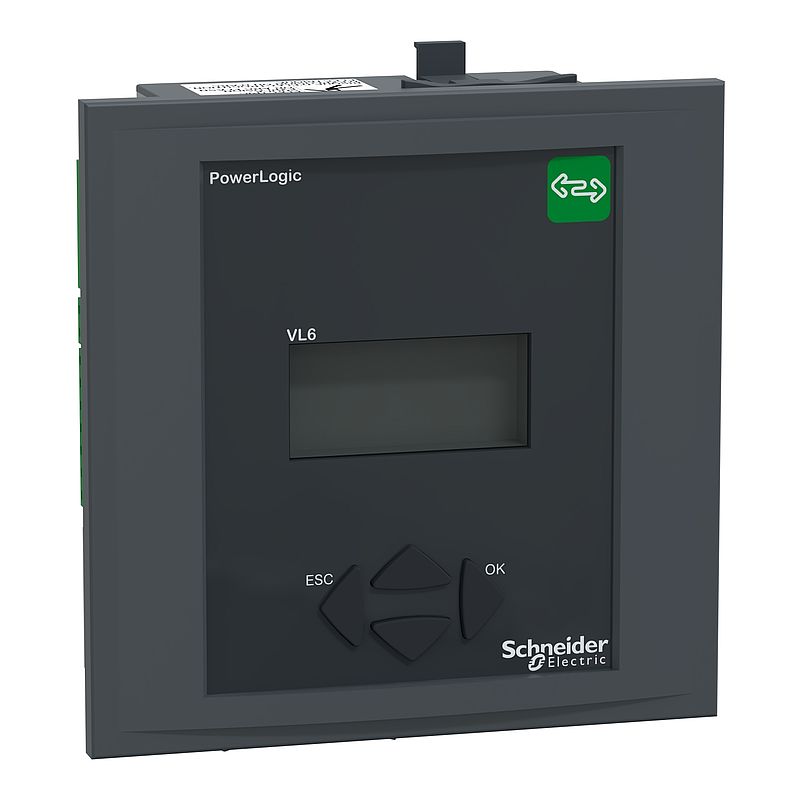
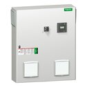
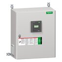
Blindleistungsregler, PowerLogic, Stufenausgangskontakte 6, VL 6
VPL06N
Materialpreisgruppe
: DL
Hauptdokumente
| Download | |
|
|
Download |
|
|
Download |
|
|
Download |
|
|
Download |
|
|
Download |
|
|
Download |
|
|
Download |
|
|
Download |
|
|
Download |
Dieses Produkt ist kompatibel mit
Hauptfunktionen: Kompatible Produkte
 Hauptfunktionen (32)
Spezifikationen
| Hauptmerkmale | |
|---|---|
| Baureihe | PowerLogic |
| Produktname | PowerLogic PFC Controller |
| Kurzbezeichnung des Geräts | VPL6 |
| Produkt- oder Komponententyp | Leistungsfaktorregler | Zusatzmerkmale |
| Anzahl der Stufenausgangskontakte | 6 |
| [UH,nom] Bemessungsbetriebsspannung | 90 - 550 V AC <= 999 kV AC mit externen VT |
| Messstrom | 0…5 A |
| Messspannung | 90…550 V AC 50/60 Hz |
| Betriebsmodus | Manuell oder automatisch |
| Anzahl der Quadranten für die Generatoranwendung | 4 |
| Geräteanschluss | Kommunikation Protokoll: Modbus Schnittstelle: RS485 |
| Eingangsfunktion | Schalter: 1 x Potentialfreier Kontakt |
| Farbcode | Frontseite: dunkelgrau RAL 7016 |
| Displaytyp | Hintergrundbeleuchtetes Display (LCD) |
| Displaygröße | 56 x 25 mm |
| Funktion verfügbar | Automatische Erkennung Fortgeschrittene Programmierung (Experte) Manuelle Programmierung Beliebige Schrittfolge Automatische Initialisierung |
| Messgerätetyp | Leistungsfaktor und Verschiebungs-PF (mit Vorzeichen, vier Quadranten) Gesamtstromverzerrung THD (I) Leistungsfaktor Durchschnitt über Lebensdauer Temperatur Maximum Phasenstrom I1, I2, I3 Effektivwert bei Last Wirkleistung P, P1, P2, P3 bei Last Blindleistung Q, Q1, Q2, Q3 bei Last Scheinleistung S, S1, S2, S3 bei Last Spannung U21, U32, U13, V1, V2, V3 bei Last |
| Messwerttyp | Umgebungstemperatur im Schaltschrank Tan φ Individuelle Oberschwingungsspannungen Cos φ Betriebszeit Leistungsfaktor Kondensatorstrom-Überlast (Irms/I1) |
| Angezeigte Informationen | Anzahl an Schaltzyklen pro Stufe Verbleibende Stufenkapazität in % Größe der einzelnen Stufen in kVAr |
| Art der Alarme | Stufenverlustleistung (< 75 %) / Aktion: Melde- und Alarmkontakt + Schritt blockiert Stufe fehlerhalft / Aktion: Melde- und Alarmkontakt + Schritt blockiert Starkstrom (> 6 A Stromwandler) / Aktion: Melde- und Alarmkontakt Nachlauf (instabile Regelung) / Aktion: Melde- und Alarmkontakt + Schritt blockiert Schwachstrom (< 15 mA CT) / Aktion: Melde- und Alarmkontakt Überkompensation / Aktion: Melde- und Alarmkontakt Kondensatorstrom-Überlast (Irms/I1) (> 130 % I1) / Aktion: Melde- und Alarmkontakt + Schritt abgeschaltet Übertemperatur (50°C) / Aktion: Melde- und Alarmkontakt + Schritt abgeschaltet Übertemperatur (30°C) / Aktion: Lüfterschalter Überspannung (+/-10 %) / Aktion: Melde- und Alarmkontakt + Steuerung angehalten Gesamt-Oberschwingungsverzerrung (> 7 %) / Aktion: Melde- und Alarmkontakt + Schritt abgeschaltet |
| Datenaufzeichnung | 5 Alarme |
| Alarm Betriebszeiten | 100000 h ohne Wartung |
| Alarm Betriebszähler | 65000 Zyklen ohne Wartung |
| Eingangstyp | Unempfindlich gegenüber der Polarität der Phasendrehung Unempfindlich gegenüber der Polarität des Wandlers Phase zu Neutralleiter Stromeingang CT...X/5 A und X/1 A Phase zu Phase |
| Ausgangstyp | Steuerrelais: 0,2 A 110 V DC Steuerrelais: 1 A 48 V DC Steuerrelais: 2 A 400 V AC 50/60 Hz Steuerrelais: 1 A 24 V DC Steuerrelais: 5 A 250 V AC 50/60 Hz Steuerrelais: 5 A 120 V AC 50/60 Hz Lüfter: 5 A 250 V AC 50/60 Hz Lüfter: 1 A 48 V DC Alarmrelais: 5 A 250 V AC 50/60 Hz Alarmrelais: 1 A 48 V DC |
| Max. an der gemeinsamen Klemme | 10 A |
| Einstellung Betriebsmodus | Manuell Automatisch |
| Art der Einstellung | Auswahl an Stufenprogrammen: autom. Auswahl an Stufenprogrammen: LIFO Auswahl an Stufenprogrammen: linear Verzögerung zwischen 2 aufeinanderfolgenden Schaltern auf der gleichen Stufe: 5 - 1.200 s Stufen-Konfigurationsprogrammierung: autom. Stufen-Konfigurationsprogrammierung: aus Stufen-Konfigurationsprogrammierung: fixiert Ziel cos phi: 0,7 induktiv - 0,7 kapazitiv Ziel cos phi: Dual cos φ |
| Messgenauigkeit | Spannung ± 1 % Strom ± 1 % Frequenz ± 1 % Energie (P,Q,S) ± 2 % Cos φ ± 2 % Summe der Oberschwingungsspannungen THD (U) ± 2 % Individuelle Oberschwingungsspannungen ± 3 % Temperatur +/-3°C |
| Zeitverzögerungsbereich | 1 - 6.500 s (bei Wiedereinschaltung) 1 - 6.500 s (bei Antwort) |
| Geliefertes Zubehör | Benutzerhandbuch |
| Montagemodus | Flächenbündig |
| Montagehalterung | Platte - Dicke: 1…3 mm |
| Montageort | Im Schaltschrank |
| Abmessungen des Ausschnitts | 138 x 138 mm |
| Höhe | 144 mm |
| Breite | 144 mm |
| Tiefe | 58 mm |
| Produktgewicht | 0,6 kg |
| Kompatibilitätscode | VPL 6 | Montage |
| Normen | IEC 61000-6-2 EN 61010-1 IEC 61000-6-4 IEC 61326-1 UL 61010-1 |
| Produktzertifizierungen | EAC NRTL cNRTL CE |
| Schutzart (IP) | Vorderseite: IP41 Rückseite: IP20 |
| Betriebshöhe | <= 2.000 m |
| Umgebungstemperatur bei Betrieb | -20…60 °C |
| Umgebungstemperatur bei Lagerung | -40…85 °C | Verpackungseinheiten |
| VPE 1 Art | PCE |
| Anzahl der Geräte pro Packung | 1 |
| Verpackungsgewicht (Lbs) | 696,000 g |
| VPE 1 Höhe | 9,200 cm |
| VPE 1 Breite | 17,800 cm |
| VPE 1 Länge | 18,400 cm |
| VPE 2 Art | S03 |
| VPE 2 Menge | 8 |
| VPE 2 Gewicht | 6,050 kg |
| VPE 2 Höhe | 30,000 cm |
| VPE 2 Breite | 30,000 cm |
| VPE 2 Länge | 40,000 cm |
| VPE 3 Art | P06 |
| VPE 3 Menge | 64 |
| VPE 3 Gewicht | 60,348 kg |
| VPE 3 Höhe | 75,000 cm |
| VPE 3 Breite | 60,000 cm |
| VPE 3 Länge | 80,000 cm | Vertragliche Gewährleistung |
| Garantie (in Monaten) | 18 |
Nachhaltigkeit
Nachhaltigkeit
|
EU-RoHS-Richtlinie
|
Konform mit Ausnahmen EU-RoHS-Deklaration |
|
Quecksilberfrei
|
Ja |
| Verpackung ohne Kunststoff | Ja |
| Verpackung mit Recycling-Karton | Ja |
| Rücknahme | Ja |
| CO2-Bilanz (kg CO2 eq.) | 227 |
| Total lifecycle Carbon footprint | 227 kg CO2 eq. |
| SCIP-Nummer | Fb1ad43d-1a69-4fc3-8936-92a443d1d0b3 |
| Carbon footprint of the manufacturing phase [A1 to A3] | 71.00331 |
| CO₂-Fußabdruck der Herstellungsphase [A1 bis A3] | 71 kg CO2 eq. |
| Carbon footprint of the distribution phase [A4] | 0.2006307 |
| CO₂-Fußabdruck der Distributionsphase [A4] | 0.2 kg CO2 eq. |
| Carbon footprint of the installation phase [A5] | 0.3001674 |
| CO₂-Fußabdruck der Installationsphase [A5] | 0.3 kg CO2 eq. |
| Carbon footprint of the use phase [B2, B3, B4, B6] | 154.82 |
| CO₂-Fußabdruck der Nutzungsphase [B2, B3, B4, B6] | 155 kg CO2 eq. |
| Sustainable packaging | Nein |
| Carbon footprint of the end-of-life phase [C1 to C4] | 0.8787 |
| CO₂-Fußabdruck der End-of-Life-Phase [C1 bis C4] | 0.9 kg CO2 eq. |
| WEEE-Kennzeichnung | Das Produkt muss entsprechend bestimmter Hinweise auf Märkten der Europäischen Union entsorgt werden und darf nicht in Haushaltsabfälle gelangen. |
| EU-RoHS-Richtlinie | Freistellungskonform |
| REACh-Verordnung | Produkt beinhaltet besorgniserregende Stoffe (SVHC) über dem Schwellwert |
17 Dokumente
| VarPlus Logic VL Benutzerhandbuch 15/09/25 · Benutzerhandbuch | 2,3 MB | Download |
| PowerLogic™ VL series Power Factor 1 Correction Controller 09/04/25 · Instruction sheet | 3,0 MB | Download |
| VPL06N China-RoHS-Erklärung
08/04/25 · Declaration of Conformity (Sustainability) |
0,2 MB | Download |
| VPL06N EU-RoHS-Erklärung
08/04/25 · Declaration of Conformity (Sustainability) |
0,2 MB | Download |
| PowerLogic™ VL series PF Correction Controller User Manual 07/04/25 · User guide | 1,7 MB | Download |
| VarPlus - Power Factor controller VarPlus Logic VPL6 and 12 - 3D CAD 15/03/25 · CAD | 1,3 MB | Download |
| PowerLogic PFC Controller, Circularity Profile, End of Life Instructions 15/03/25 · Circularity Profile | 0,4 MB | Download |
| DoC DE upd23 15/03/25 · Certificate | 1,3 MB | Download |
| PowerLogic™ VL series (VL6, VL12) Power Factor Correction Controller 15/03/25 · Instruction sheet | 1,8 MB | Download |
| Declaratie de conformitate VarPlus Logic 15/03/25 · Declaration of conformity | 1,2 MB | Download |
| VarPlus Logic SE Driver for PME 2020 (ENG)
15/03/25 · Software - Hotfix |
4,0 MB | Download |
| VarPlus Logic SE Driver for PME 9.0 (ENG)
15/03/25 · Software - Hotfix |
4,6 MB | Download |
| VarPlus Logic Technical drawings 15/03/25 · Technical Drawing | 0,1 MB | Download |
| VarPlusLogic declaration of conformity 15/03/25 · Declaration of conformity | 0,7 MB | Download |
| VarlogicRT declaration of conformity 15/03/25 · Declaration of conformity | 0,7 MB | Download |
| VPL06N REACh-Erklärung
06/11/24 · Declaration of Conformity (Sustainability) |
0,2 MB | Download |
| 01/01/70 Environmental Disclosure | 0,0 MB | Download |

